8 Two-Lane Highway Quick Editor
8.1 Main Input Screen
The main input screen (See Figures below) is where the roadway geometry is specified. This is done by adding segments/links where you can set the length, initial angle, free-flow speed, grade, and so on. Click ‘Add New Link’ to add a new roadway segment, click ‘Insert New Link’ to add a new roadway segment above the current segment you have selected, click ‘Delete Link’ to delete the currently selected segment.
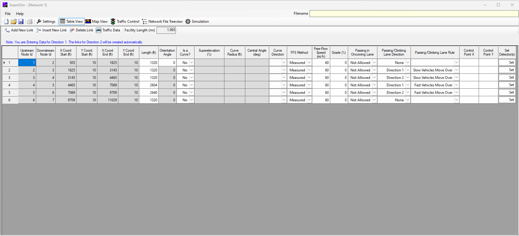
Figure 8.1: Two-Lane Highway Facility Quick Editor
8.2 Segment Input Fields
Links and their corresponding characteristics are specified for the west-to-east or north-to-south travel direction (considered ‘Direction 1’) and the inputs for the opposing travel direction (considered ‘Direction 2’) are automatically created by the program.
8.2.1 Upstream/Downstream Node ID
The node ID values are automatically created upon adding/inserting a new link. These same node ID values are used for the links in the opposing direction (which again, are created automatically by the program). Thus, the link ID for the opposing direction for link ID ‘12’ would be ‘21’, ID ‘32’ for the opposing direction link to link ID ‘23’, and so on.
8.2.2 X Coord Start/X Coord End and Y Coord Start/Y Coord End
The start and end coordinates for each segment. These values are automatically created, based on the length and orientation angle, and horizontal curve inputs.
8.2.3 Length
For tangent segments, the link length is entered in this cell. For curved links, the link length will be based on the curve radius and central angle. Consequently, the length cell for a curved link will be colored gray, indicating that it cannot be edited directly. User input of length is restricted to integer values; however, the program may replace entered values with decimal values as a consequence of curved links and/or coordinate point adjustments.
8.2.4 Horizontal Curve Specific Inputs
If the segment corresponds to a horizontal curve, select ‘Yes’ for “Is a Curve?”. If this is done, additional segment inputs will be enabled, specifically: superelevation, curve radius, central angle, and curve direction (this latter input corresponding to the general turning direction of the curve). Filling in the central angle and radius of the curve will automatically adjust the segment length and control points accordingly.
8.2.5 2 + 1 Section
Not currently functional. The intent for this future feature is to be able to display a 2+1 section as a 3-lane section, with the passing lanes in the middle of the section. A 2+1 section can still be simulated by combining passing lane segments and non-passing lane segments. In this case, however, the passing lanes will be to the right of the regular lanes. You will also need to specify “fast vehicles move over” for the passing lane rule.
8.2.6 Control Point X/Control Point Y
These input fields will only be editable for curved links.
Inputs not discussed in this section, as well as more information on the inputs mentioned here, are described in the Network Structure chapter.
8.2.6.1 Detectors
Detectors allow one to set points along the segment to measure specific traffic flow parameters, such as speed, volume, etc. To set detectors on a segment click on ‘Set’ under ‘Set Detector(s)’ to open the Detectors dialogue box. A detector’s location along the segment is specified by a percentage of the length of the segment. For example, with a 5280-ft segment, a detector set at 25% would be located at 1320 ft in the travel direction. Click ‘OK’ when done.
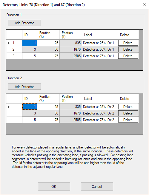
Figure 8.2: Two-Lane Highway Detector Entry Form
8.2.7 Entering Traffic Data
Press the ‘Traffic Data’ button in the toolbar near the top of the screen to access the ‘Entry Link Inputs’ form (see Figures below).
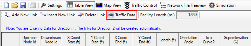
Figure 8.3: Two-Lane Highway Traffic Data Toolbar Button
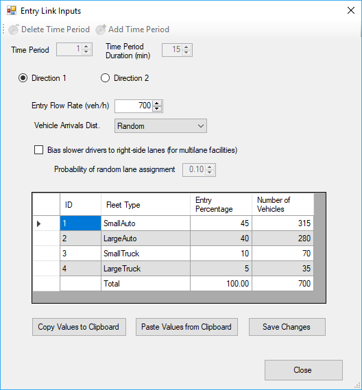
(#fig:TwoLaneTrafficData.png)Two-Lane Highway Traffic Data Entry Screen
In this screen, the overall entry flow rate per direction and the percentage split for each vehicle type can be specified. After setting values for ‘Direction 1’, press the ‘Save Changes’ button before selecting ‘Direction 2’. After setting values for ‘Direction 2’, press the ‘Save Changes’ button again before closing the form.
To save your created network and traffic data to disk, see User Interface Overview.