6 Network Structure
6.1 Overview
A SwashSim network is composed of the following components:
Nodes (entry, connector, exit)
- Entry
- Vehicles enter the network at entry nodes
- ID numbering: Entry node numbering starts at 701 and increments by 1 with each successive entry node added to the network
- Exit
- Vehicles exit the network at entry nodes
- ID numbering: Exit node numbering starts at 801 and increments by 1 with each successive exit node added to the network
- Ramp connector
- Used to identify a link as an on- or off-ramp connecting to a freeway mainline segment
- ID numbering: Ramp connector node numbering starts at 601 and increments by 1 with each successive ramp connector node added to the network
- Connector
- Connector nodes are used in all other link connection circumstances
- Entry
Links (entry, connector, exit)
- Each link is bounded by an upstream node and downstream node
- ID numbering: Concatenation of upstream and downstream node ID’s, in direction of travel
The upstream and downstream links that each link connects to must be specified (entry links have no upstream connecting links and exit links have no downstream connecting links)
Lanes
- ID numbering
- From outside to inside (lane 1 is outer most lane)
- Types
- Regular, Left Turn Bay, Etc.
- ID numbering
The upstream and downstream lanes that each lane connects to must be specified
Control Points
- These are placed at various positions within a lane and are tied into signalized, unsignalized, and ramp metering control logic.
Detectors
- Detectors allow one to set points along a link to measure specific traffic flow parameters, such as speed, volume, etc. Detectors are also used with actuated signal and ramp metering control.
6.2 Node Properties
6.2.1 X/Y Coordinates
Each coordinate has an X and Y position. The units are feet. However, the absolute coordinate values are irrelevant–only the relative coordinate positions between nodes are relevant to the internal SwashSim calculations. In the Freeway and Two-Lane Highway modules, these coordinate values are automatically created (as a function of link length, orientation, and curvature). In the Custom network creation module, these coordinate values must be explicitly specified.
6.3 Common Link Properties
6.3.1 Upstream/Downstream Node ID
A link has a beginning (upstream) and ending (downstream) node. Link ID values are created by concatenating the upstream and downstream node ID values. For example, Link ID ‘12’ corresponds to a link that has upstream node ID ‘1’ and downstream node ID ‘2’. The upstream and downstream node IDs are set automatically in the various network creation user interface (UI) screens. However, those values can be overridden by the user in the ‘Custom’ network creation module.
6.3.2 Length
Freeway and Two-Lane Highway modules: For tangent segments, the link length is entered in this cell. For curved links, the link length will be based on the curve radius and central angle. Consequently, the length cell for a curved link will be colored gray, indicating that it cannot be edited directly. User input of length is restricted to integer values; however, the program may replace entered values with decimal values as a consequence of curved links and/or coordinate point adjustments.
Custom network module: The length is automatically calculated for both tangent and curved links. It is based on the entered upstream and downstream node coordinate values, as well as the control point coordinate values for curved links.
6.3.3 Orientation Angle
This input corresponds to a compass angle based on the direction of travel.
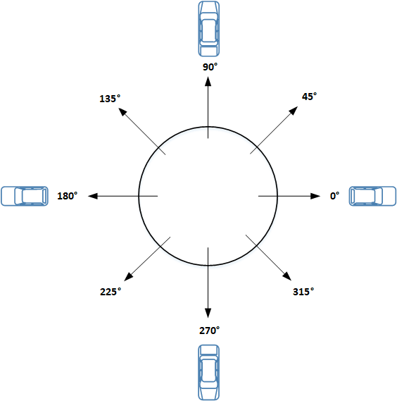
Figure 6.1: Orientation Angle
For example, the segment angle would be set as follows for the given travel directions:
- \(0^\circ\) for perfectly horizontal east-to-west travel
- \(180^\circ\) for perfectly horizontal west-to-east travel
- \(90^\circ\) for perfectly vertical south-to-north travel
- \(270^\circ\) for perfectly vertical north-to-south travel.
In the Freeway and Two-Lane Highway quick editor screens, the orientation angle only needs to be specified for the first link. Subsequent link orientation angles are calculated by the program and are a function of the previous link orientation angle and any specified horizontal curvature. In the Custom network creation module, the orientation angle is calculated by the program, based on the entered node coordinate positions.
6.3.4 Horizontal Curvature
A link can either be straight (i.e., tangent) or curved. If it is a curved link, additional inputs are required, specifically:
6.3.4.1 Control Point X/Y Coordinates
Horizontal curves are represented as a 3-point (quadratic) Bezier curve. The control point is a point in between the link start and end points that affects the amount of curvature of the link. In the freeway and two-lane highway network creation modules, these values are set to provide as close a match as possible to the alignment of the curve per the circular curve inputs of radius and central angle. In the Custom network creation module, the control point inputs are used in lieu of curve radius and central angle inputs.
6.3.5 Grade
The percent incline or decline of the segment. This is measured as the elevation change over the length of the segment divided by the segment length, multiplied by 100.
6.3.6 Free-Flow Speed
For tangent links, the free-flow speed must be explicitly specified. For curved links, the free-flow speed can be explicitly specified or it can be estimated. In the latter case, the free-flow speed is estimated according to the model discussed [[Desired Speed|here]]. Units of entry are ft/s.
6.3.7 Downstream Vehicle Turning Percentages
Currently, the assignment of a vehicle’s turning movement (left, through, or right) at the end of its current travel link is done at the moment it exits its previous travel link. This turning movement assignment is performed by drawing a uniform random number (between 0 and 1) and comparing to the specified turning percentages. The specified turning movement percentages can be applied to all vehicle fleet types equally, or can be varied by fleet type. The latter condition is useful, for example, in situations where one of the downstream connecting links connects to a route that prohibits large trucks.
6.3.8 Upstream/downstream connecting link ID’s
- The upstream and downstream links that each link connects to must be specified
- Entry links have no upstream connecting links–ID values should be set to zero
- Exit links have no downstream connecting links–ID values should be set to zero
- An example of how to code these connections is shown below
6.3.9 Upstream/downstream connecting lane ID’s
- The upstream and downstream lanes that each lane connects to must be specified
- Lanes that have no upstream connecting lane (e.g., a left-turn bay) should have a connecting ID value of zero
- Lanes that have no downstream connecting lane (e.g., an acceleration) should have a connecting ID value of zero
- An example of how to code these connections is shown below
6.4 Two-lane highway-only Link Properties
6.4.1 Passing in Oncoming Lane
The options for passing in the oncoming lane are:
- Allowed ‘Direction 1’
- Allowed ‘Direction 2’
- Allowed Both Directions
- Not Allowed
6.5 Lane Data
6.5.0.1 Lane Types
- Regular - A lane that always extends the full length of a link. Left, through, and right turn movements can be assigned to this lane type.
- Turn Bay Left - A left turn bay can be set to a length shorter than the full length of the link. The turn bay lane will always terminate at the downstream end of link.
- Turn Bay Right - A right turn bay can be set to a length shorter than the full length of the link. The turn bay lane will always terminate at the downstream end of link.
- Acceleration - An acceleration lane can be set to a length shorter than the full length of the link. Such a lane will always start at the upstream end of link. A distinguishing feature of an acceleration lane is that when a vehicle enters such a lane, from an on-ramp for example, the vehicle will immediately be tagged as needing to make a Mandatory Lane Changing and will look to move into the adjacent lane as soon as it identifies a suitable gap. For a regular lane that does not connect to a lane on the downstream link, a vehicle may make a Discretionary Lane Changing into the adjacent lane well upstream of the end of the lane, but it will not get tagged to make a mandatory lane change until it gets close to the point where it would have to begin slowing to a stop to avoid running off the end of the lane if it is not able to move to the adjacent lane.
- Deceleration - An deceleration lane can be set to a length shorter than the full length of the link. Such a lane will always terminate at the downstream end of link. Similar to an acceleration lane, a vehicle destined for a deceleration lane, to access an off-ramp for example, will look to move into the deceleration as soon as it identifies a suitable gap.
- Auxiliary - An auxiliary lane is a continuous lane connecting a freeway on-ramp to an off-ramp, a configuration often seen in ‘weaving’ sections. This lane type essentially combines the characteristics of an acceleration lane and a deceleration lane.
- Passing Lane - Used with the ‘Two-Lane Highway Passing Lane’ link type. This lane has additional properties that can be defined that affect the passing, or not-passing, behavior of vehicles within this link.
- Passing Oncoming Lane - Used with the ‘Two-Lane Highway Basic’ link type. When specifying this link type, the lane used for passing in the oncoming direction will be automatically set up by the program.
- Median - Currently, the only option for this ‘lane’ type is a raised median–it cannot be used for vehicle travel; thus, it is ignored in all vehicle movement logic. In the animation, it will have a green background color. A median lane cannot be used on entry or exit links.
It should be noted that certain vehicle movement behavior can be obtained with more than one lane type. In some cases, however, the lane type can help bypass certain portions of the vehicle movement logic and potentially reduce the simulation time. As one example, a regular lane could be set up to allow only left-turn movements. However, for a vehicle making a through movement to the next link, such a lane would still be checked as a possibility for discretionary lane changes. Once the allowed movement (i.e., left only) of the lane is checked, it would be ruled out for a lane change candidate. But the additional step of checking the allowed movements for the lane can be skipped altogether once the initial check of the lane type (i.e., left turn bay) is made.
Another note regarding lanes designated for only a turning movement–a turn bay can also be created with a separate link, adjacent to another link that allows other movements. In this situation, vehicles will only be able to enter the turn bay at the beginning the link. This would be appropriate for situations in which there is a median or another separation method, such as ‘candlestick’ style traffic cones or a low-profile curb, separating the turn bay from the adjacent lanes. If the turn bay lane type is part of a link with other lanes, vehicles will be able to move into the turn bay lane at any point along its full length.
6.5.0.2 Lane Turn Movements
- Through Only
- Right Only
- Left Only
- Through + Right
- Through + Left
- Left + Right
- Through + Right + Left
6.5.1 Lane Objects
Detector and traffic control point objects can be placed within individual lanes of a link. Information about how to insert detectors and control points can be found in the following three chapters.
6.5.1.1 Detectors
Detectors are objects that can be placed in individual lanes of a link to record various measures of passing vehicles, as indicated in the Performance Measures. Detector objects are point detectors and generally measure vehicle operational attributes, such as speed, instantaneously, at the time the front edge of a vehicle crosses the leading (upstream) edge of a detector.
Detectors do have a length property so they can also mimic the operation of a physical inductance loop detector (ILD). The default length is 6 ft but can be changed as necessary. The length is used for the purpose of replicating the measurement of lane occupancy. See the Performance Measures chapter for more information about the lane occupancy measurement. The time a detector is occupied by a vehicle is counted from the time the front edge of a vehicle passes the leading (upstream) edge of the detector until the rear edge of the vehicle passes the downstream edge of the detector.
A single physical ILD cannot directly measure vehicle speed because the length of any given vehicle crossing the detector is not known. Thus, to measure speed, two detectors are placed closely together (far enough apart to avoid electrical interference between the two, but close enough such that any change in vehicle speed between the two detectors will be negligible. With this setup, the speed is calculated as the distance between the leading edges of the two detectors (usually about 6 feet) divided by the difference in actuation times of the respective detectors. This approach is not need in simulation since the simulation engine keeps track of all vehicle properties for every simulation time step.
Available detector functions:
- Unassigned - use this function when the detector will only used for recording traffic stream measurements
- Actuated Signal - use this function for registering vehicle calls with an actuated signal controller
- Ramp Meter Mainline - use this function for coordinating freeway mainline traffic performance measurements with a traffic-responsive ramp metering control algorithm
- Ramp Meter Presence - use this function for identifying when a vehicle is waiting at a ramp meter signal
- Ramp Meter Passage - use this function for identifying when a vehicle has passed beyond a ramp meter signal
- Ramp Meter Queue Intermediate - use this function for coordinating on-ramp intermediate queue spillback measurements with a traffic-responsive ramp metering control algorithm
- Ramp Meter Queue Advance - use this function for coordinating on-ramp advance (i.e., start of ramp) queue spillback measurements with a traffic-responsive ramp metering control algorithm
6.5.1.2 Traffic Control Points
Traffic control points provide a mechanism to facilitate interaction between vehicles and traffic control devices. For example, they are utilized at a signalized intersection to “communicate” the displayed signal indication to a specific lane on an approach link. Control points are placed within lanes of a link. Generally, they are placed at the location where you want the vehicle to respond to it. In the case of a signalized intersection or approach controlled by a stop sign, this position would correspond to the stop bar location.
Available control point types:
- Signalized
- Ramp meter
- Stop
- Yield
6.6 Upstream/Downstream Connecting Link/Lane IDs Example
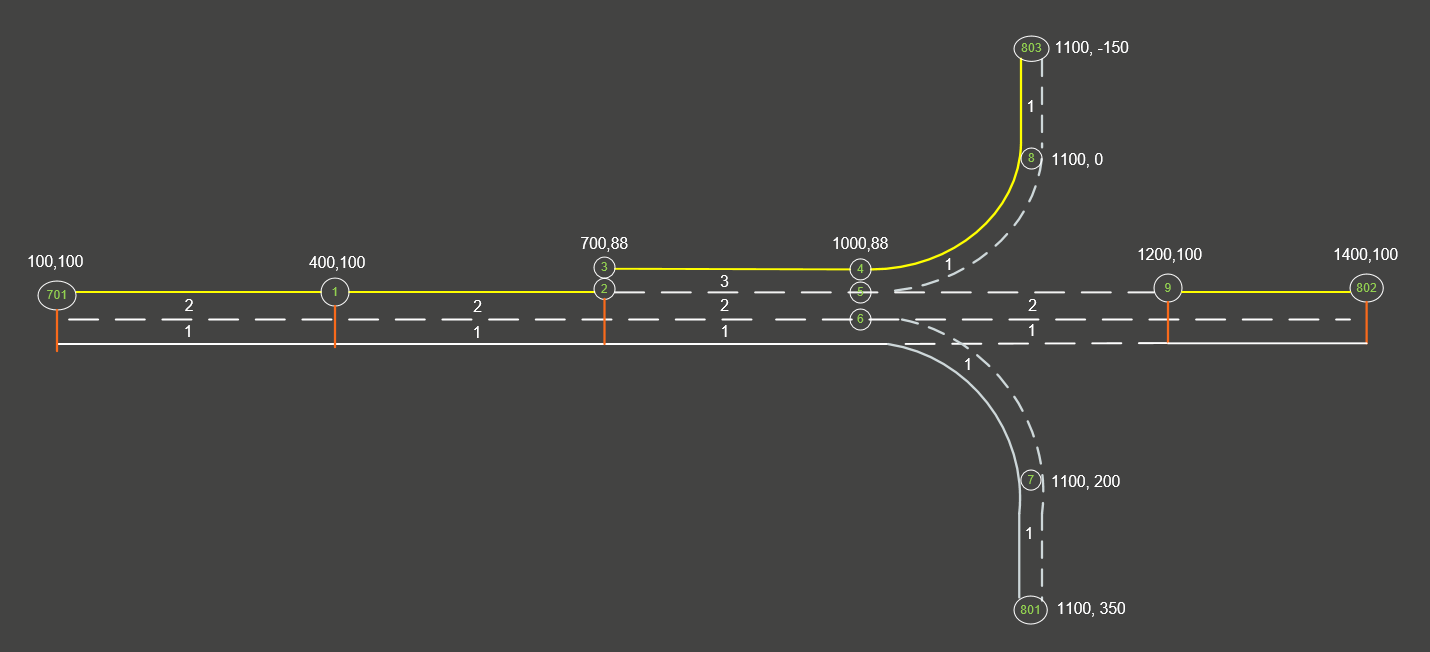
Figure 6.2: Sample Network
6.6.0.1 Nodes
|
Node ID |
Coordinates |
Connected Links |
|
|
X |
Y |
||
|
701 |
100 |
100 |
7011 |
|
1 |
400 |
100 |
7011, 12 |
|
2 |
700 |
100 |
12 |
|
3 |
700 |
88 |
34 |
|
4 |
1000 |
88 |
34, 48 |
|
5 |
1000 |
100 |
59 |
|
6 |
1000 |
112 |
67 |
|
7 |
1100 |
200 |
67, 7801 |
|
8 |
1100 |
0 |
48, 8803 |
|
9 |
1200 |
100 |
59, 9802 |
|
801 |
1100 |
350 |
7801 |
|
802 |
1400 |
100 |
9802 |
|
803 |
1100 |
-150 |
8803 |
6.6.0.2 Connecting Link IDs
|
Link ID |
Upstream Connecting Link ID |
Downstream Connecting Link ID |
||||
|
Left |
Through |
Right |
Left |
Through |
Right |
|
|
7011 |
0 |
0 |
0 |
0 |
12 |
0 |
|
12 |
0 |
7011 |
0 |
0 |
34 |
0 |
|
34 |
0 |
12 |
0 |
48 |
59 |
67 |
|
67 |
0 |
34 |
0 |
0 |
7801 |
0 |
|
59 |
0 |
34 |
0 |
0 |
9802 |
0 |
|
48 |
0 |
34 |
0 |
0 |
8803 |
0 |
|
7801 |
0 |
67 |
0 |
0 |
0 |
0 |
|
9802 |
0 |
59 |
0 |
0 |
0 |
0 |
|
8803 |
0 |
48 |
0 |
0 |
0 |
0 |
6.6.0.3 Connecting Lane IDs
|
Link ID |
Lane ID |
Upstream Connecting Lane ID |
Downstream Connecting Lane ID |
||||
|
Left |
Through |
Right |
Left |
Through |
Right |
||
|
7011 |
1 |
0 |
0 |
0 |
0 |
1 |
0 |
|
2 |
0 |
0 |
0 |
0 |
2 |
0 |
|
|
12 |
1 |
0 |
1 |
0 |
0 |
1 |
0 |
|
2 |
0 |
2 |
0 |
0 |
2 |
0 |
|
|
34 |
1 |
0 |
1 |
0 |
0 |
1 |
1 |
|
2 |
0 |
2 |
0 |
0 |
2 |
0 |
|
|
3 |
0 |
0 |
0 |
1 |
0 |
0 |
|
|
67 |
1 |
0 |
1 |
0 |
0 |
1 |
0 |
|
59 |
1 |
0 |
1 |
0 |
0 |
1 |
0 |
|
2 |
0 |
2 |
0 |
0 |
2 |
0 |
|
|
48 |
1 |
0 |
3 |
0 |
0 |
1 |
0 |
|
7801 |
1 |
0 |
1 |
0 |
0 |
0 |
0 |
|
9802 |
1 |
0 |
1 |
0 |
0 |
0 |
0 |
|
2 |
0 |
2 |
0 |
0 |
0 |
0 |
|
|
8803 |
1 |
0 |
1 |
0 |
0 |
0 |
0 |