28 Two-Lane Highway Modeling
Detail about the logic used for two-lane highway passing maneuvers is provided here. Additional information is provided in Li and Washburn (2011).
28.1 Passing Modes
There are multiple passing modes that a vehicle may be in, as follows:
- Not Passing
- Passing Oncoming Initial
- Passing Oncoming Normal
- Passing Oncoming Abort Min
- Passing Oncoming Abort Med
- Passing Oncoming Abort Max
- Passing Oncoming Expedite Min
- Passing Oncoming Expedite Med
- Passing Oncoming Expedite Max
- Passing Lane Initial
- Passing Lane Normal
- Passing Lane Abort
- Passing Lane Expedite
- Passing Oncoming Cooperation Min
- Passing Oncoming Cooperation Med
- Passing Oncoming Cooperation Max
Definitions forthcoming.
28.2 Passing in Oncoming Lane
The most distinguishing feature of traffic operations on two-lane highways is passing in the oncoming lane (when passing lanes are not present). Therefore, this passing maneuver is constrained by not only the amount of opposing-lane distance used in the execution of a passing maneuver, but also the sight distance and clear-distance (or gap size) a follower requires before attempting a passing maneuver. The former issue depends on road design and markings of a no-passing zone, while the latter issue depends on traffic demands. The following subsections describe the various components of logic employed to determine when and how a vehicle will perform a passing maneuver in the oncoming lane.
When will a vehicle attempt to pass a vehicle in front of it?
1. Determine if the subject vehicle is in a following mode
Currently, the program defines a vehicle as being in a following mode when the time headway between it and the vehicle immediately in front of it is equal to or less than or equal to 2.5 s—this is currently the logic the HCM (Transportation Research Board and National Academies of Sciences, Engineering, and Medicine (2022)) uses to approximate % Followers. The value of 2.5 s, however, can be changed by the analyst in the settings. Additionally, the trailing vehicle must be traveling at a speed at least equal to the speed of the leading vehicle. If the subject vehicle is determined to be in a following mode, then the following steps are carried out to determine if the following vehicle will attempt a passing maneuver.
2. Determine tolerable speed
If it is determined that a vehicle is in a following mode, then the tolerable speed for that vehicle is calculated. Tolerable speed is defined as the maximum speed at which the desire to pass for a following driver will be 100 percent. Tolerable speed varies for different driver types (See following equation), due to the different degree of aggressiveness for each driver type. Note that a driver’s desired speed is a function of free-flow speed and driver type. For example, a driver of type 1 will have a desired speed of 88% of the link free-flow speed, while a driver of type 10 will have a desired speed of 112% of the link free-flow speed (these percentages of free-flow speed can be modified by users in the Driver Settings).
\[TolerableSpee{d_i}=DesiredSpee{d_i}\times\frac{80+i}{100}\]
where:
\({TolerableSpeed_i} = \text{tolerable speed for driver type } i \text{ (mi/h)}\),
\({DesiredSpeed_i} = \text{desired speed for driver type } i \text{ (mi/h), and}\)
\(i = \text{driver type, a value between 1 and 10 for default settings.}\)
3. Determine the desire to pass
The main factor influencing a driver’s desire to pass is the difference between their actual travel speed and their desired speed. The degree of the following driver’s desire to pass is quantified as a number between 0 and 1, based on a non-linear function of the current speed of the subject vehicle. The initial desire to pass (DTP) value is given by
\[ DTP=\left\{\begin{array}{l} 1 &\mbox{if CurrentSpeed < TolerableSpeed}\\ 0 &\mbox{if CurrentSpeed $\geq$ DesiredSpeed}\\ [0.95\times (DesiredSpeed-CurrentSpeed) \times\frac{1}{0.95 \times DesiredSpeed-TolerableSpeed}]^4 &\mbox{elsewhere} \end{array}\right. \]
The DTP is illustrated graphically in the figure below for one example driver.
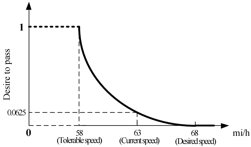
Figure 28.1: Desire To Pass for Example Driver
The DTP value is adjusted by an impatience factor. For vehicles that have a positive DTP, but are in a following mode and have not yet initiated a passing maneuver, the impatience factor will incrementally increase the DTP value with each simulation time step; thus increasing the probability of a passing maneuver being initiated. The impatience factor is also a function of the driver type, with larger increments being associated with more aggressive drivers. The impatience factor is given by
\[ImpatienceFactor=TSWTP\times ImpatienceValue \times \sqrt{DT}\]
where:
\({TSWTP} = \text{time spent wanting to pass (s)}\),
\({ImpatienceValue} = \text{degree of impatience in waiting to pass (default = 0.001), and}\)
\({DT} = \text{driver type, a value between 1 and 10 for default settings.}\)
The TSWTP counter will initiate when a vehicle has a DTP value greater than zero and will reset when the vehicle completes a pass or its DTP value goes to zero. Finally, the DTP is also adjusted based on the length of the trailing vehicle and the length of the leading vehicle. A longer leading vehicle, such as a large truck, will increase the DTP value for the trailing vehicle. Conversely, the DTP value will be decreased for a longer trailing vehicle. The adjustment to the DTP value for the leading and trailing vehicle lengths is given by
\[AdjDTP=(DTP+ImpatienceFactor)\times [1-(\frac{1}{14}-\frac{1}{SubjectVehLength})]\times \ln[\exp(1)-(\frac{1}{14}-\frac{1}{LeadVehLength})]\times\sqrt{\frac{LeadVehLength}{SubjectVehLength}}\]
where:
\({14} = \text{constant corresponding to shortest vehicle length (ft) used in SwashSim}.\)
The adjusted DTP value is then compared to a generated uniform random number between 0 and 1. If the adjusted DTP value is less than the random number, the subject vehicle will continue to follow the leading vehicle. If the adjusted DTP value is greater than or equal to the random number, the subject vehicle will initiate a passing maneuver, subject to other constraints as described in the following section.
Constraints governing whether a pass will be initiated
If it has been determined that a vehicle wants to initiate a passing maneuver, the following issues are considered.
1. Is the vehicle in a passing-allowed section?
The program logic currently dictates that all passing maneuvers must be initiated in a passing-allowed section of the roadway (i.e., skip striping in the applicable direction).2 However, it is possible for a passing maneuver to be completed in a no-passing-allowed section, consistent with the field observations from Douglas W. Harwood et al. (2008). This is described in more detail under step 7.
2. Check whether a vehicle upstream of the subject vehicle is performing a passing maneuver
If the subject vehicle is currently in the process of being passed by another vehicle, the subject vehicle will not initiate its passing maneuver.
3. Check whether the maximum number of allowed passing maneuvers is currently in progress
The number of vehicles that can be simultaneously executing a passing maneuver in the oncoming lane is limited to three per each platoon of vehicles. Thus, the maximum number of vehicles that can be executing a passing maneuver along the defined length of highway is three times the number of platoons within that defined length of highway. A platoon is defined by a leading vehicle that is not in a following mode and trailing vehicles that are all considered to be in a following mode.
4. Check the number of vehicles that must be passed to complete the passing maneuver
A vehicle is prevented from starting a passing maneuver when, due to insufficient gaps for merging between the vehicles ahead, there are more than 5 vehicles that would need to be passed.
5. Determine the required passing sight distance
If the subject vehicle is allowed to initiate a passing maneuver per the above constraints, then the passing sight distance (PSD) will be calculated. PSD is the minimum distance necessary between the potential passing vehicle and an oncoming vehicle that will still allow the potential passing vehicle to safely initiate and complete a passing maneuver of a leading slower vehicle in the oncoming lane. If the horizontal and/or vertical alignment aspects of a highway do not provide unobstructed sight distance at least equal in length to the PSD, then the highway is typically striped with solid yellow center lines (i.e., no-passing allowed).3 Both A policy on Geometric Design of Highways and Streets (AASHTO (2004)) and the Manual on Uniform Traffic Control Devices for Streets and Highways (MUTCD) (FHWA (2003)) provide minimum PSD values for design and marking. However, their respective recommended PSD values vary significantly, with the AASHTO-recommended values being considerably larger than the MUTCD-recommended values.
Douglas W. Harwood et al. (2008) proposed recommendations on the adequacy of current procedures and guidelines used to estimate minimum PSD requirements for highway design and pavement marking. The research involved a review of current practice, an extensive analysis of various alternative PSD models, and field studies of passing maneuvers on two-lane highways. Field studies conducted in Missouri and Pennsylvania, together with field data from Texas as part of another study (Carlson, Miles, and Johnson (2006)), were used to characterize driver behavior and quantify traffic performance measures for passing maneuvers. Based on the literature review and the field study, Douglas W. Harwood et al. (2008) indicated that the Glennon (1988) model and the Hassan, Easa, and El Halim (1996) are the most reasonable models. The Glennon (1988) and Hassan, Easa, and El Halim (1996) models result in considerably shorter PSD values than the AASHTO-recommended values, much closer to the MUTCD-recommended values. The main reason for this is because the Glennon (1988) and Hassan, Easa, and El Halim (1996) models consider that a passing vehicle can easily abort the passing maneuver before it reaches the critical position4; thus, contending that the necessary PSD really only needs to be considered from the critical position and not for the entire length of the passing maneuver. Furthermore, the Douglas W. Harwood et al. (2008) study argued that crash statistics for two-lane highways do not provide much support for the notion that the current practice for marking passing zones (based on the MUTCD criteria) is in need of revising.
Based on the field data results of the Douglas W. Harwood et al. (2008) study, the authors recommend the following assumptions be used when applying the Glennon (1988) and Hassan, Easa, and El Halim (1996) models:
1. The speeds of the passing and opposing vehicles are equal and represent the design speed of the highway.
2. The passed vehicle travels at uniform speed and the speed difference between the passing and passed vehicles is 12 mi/h.
3. The passing vehicle has sufficient acceleration capability to reach the specified speed difference relative to the passed vehicle by the time it reaches the critical position. (same as the assumption that each vehicle will travel at the constant speed after the critical position)
4. The lengths of the passing and passed vehicles are 19 ft.
5. The passing driver’s perception-reaction time in deciding to abort a passing vehicle is 1 s.
6. The deceleration rate used in aborting a pass is 11.1 ft/s2.
7. For a completed or aborted pass, the headway between the passing and passed vehicles is 1 s.
8. The minimum clearance headway between the passing and opposing vehicles at the point at which the passing vehicle returns to its normal lane is 1 s.
Using these assumptions in the Glennon (1988) and Hassan, Easa, and El Halim (1996) models results in PSD values similar to the MUTCD-recommended PSD values, as illustrated in the following figure.
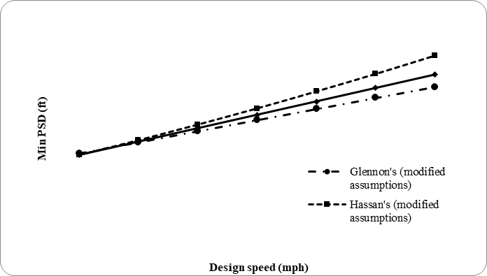
Figure 28.2: Comparison of PSD Values
Therefore, Douglas W. Harwood et al. (2008) recommended that AASHTO adopt the MUTCD PSD values for inclusion in the next edition of A policy on Geometric Design of Highways and Streets. These MUTCD values are justified since they are consistent with the values produced by the Glennon (1988) and Hassan, Easa, and El Halim (1996) models when used with input values based on current field observations.
The default PSD model used in SwashSim is the AASHTO model. However, it is also possible to use the MUTCD PSD values instead. The AASHTO PSD model is presented first, followed by the modifications necessary to implement the MUTCD PSD values.
|
Component of passing maneuver |
Speed range (mi/h) |
|||
|
|
30-40 |
40-50 |
50-60 |
60-70 |
|
|
Average passing speed (mi/h) |
|||
|
|
34.9 |
43.8 |
52.6 |
62.0 |
|
Initial maneuver |
||||
|
a (ft/s/s) |
1.40 |
1.43 |
1.47 |
1.50 |
|
t1 (s) |
3.6 |
4.0 |
4.3 |
4.5 |
|
d1 (ft) |
\(1.467{t_1}\left({v - m + \frac{{a{t_1}}}{2}} \right)\) |
|||
|
Occupation of left lane |
||||
|
t2 (s) |
9.9a |
|||
|
d2 (ft) |
\(1.467v{t_2}\) |
|||
|
Clearance distance |
||||
|
d3 (ft) |
100 |
180 |
250 |
300 |
|
Opposing vehicle |
||||
|
d4 |
0.667 × d2 |
|||
|
Minimum PSD |
d 1 + d2 + d3 + d4 |
|||
a The original AASHTO criteria included four separate values for \(t_2\), based on the passing vehicle speed. The Douglas W. Harwood et al. (2008) study did not “…provide any evidence to support the hypothesis that the left lane travel time increases with increasing passed vehicle speed. Therefore, it is recommended that a constant value of \(t_2\), independent of speed, should be used…”. The chosen value was the mean value of 9.9 seconds from their study.
where:
\(d_1 = \text{initial maneuver—distance traveled from start of passing maneuver until passing vehicle encroaches upon oncoming lane (ft)}\),
\(t_1 = \text{time required for initial maneuver (s)}\),
\(a = \text{acceleration of passing vehicle when initiating passing maneuver (mi/h/s)}\),
\(v = \text{average speed of passing vehicle (mi/h)}\),
\(m = \text{difference in speed of passed vehicle and passing vehicle (mi/h)}\),
\(d_2 = \text{the distance traveled by the passing vehicle from the point of encroachment in the oncoming lane to the point of return to the normal lane (ft)}\),
\(t_2 = \text{time spent traveling in the oncoming lane (s)}\),
\(d_3 = \text{the shortest desirable distance between the front bumpers of the passing and opposing vehicle when the passing vehicle returns to the normal lane (ft), and}\)
\(d_4 = \text{the distance traveled by the opposing vehicle during the time the passing vehicle travels from the position of being directly abreast of the vehicle being passed to the return to the normal lane (ft)}\).
The PSD distance components are illustrated in the following figure.
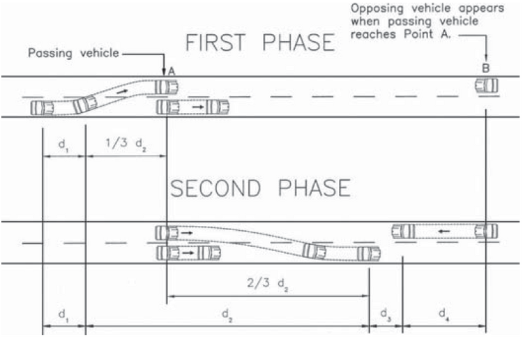
Figure 28.3: Elements of Passing Sight Distance for Two-lane Highways (AASHTO (2004))
For computational convenience, the same formulas used in the AASHTO PSD model are used for generating the MUTCD PSD values. To implement the MUTCD PSD values in SwashSim, the values shown in the table above should be revised as shown in the following Table. These values can be changed in the settings.
|
Component of passing maneuver |
Speed range (mi/h) |
|||
|
30-40 |
40-50 |
50-60 |
60-70 |
|
|
Average passing speed (mi/h) |
||||
|
34.9 |
43.8 |
52.6 |
62.0 |
|
|
Initial maneuver |
||||
|
𝑡1 (s) |
3.0 |
2.5 |
2.0 |
1.6 |
|
Occupation of left lane |
||||
|
𝑡2 (s) |
5.9 |
6.0 |
6.2 |
6.4 |
|
Clearance distance |
||||
|
𝑑3 (ft) |
80 |
100 |
120 |
140 |
The following table shows the PSD values computed with the revised variable values as well as the actual MUTCD-recommended PSD values. The approximated MUTCD PSD values compare very favorably with the actual PSD values.
|
Design speed (mi/h) |
|||||||
|
40 |
45 |
50 |
55 |
60 |
65 |
70 |
|
|
Modified AASHTO PSD (ft) |
605 |
708 |
801 |
909 |
1000 |
1111 |
1202 |
|
MUTCD PSD (ft) |
600 |
700 |
800 |
900 |
1000 |
1100 |
1200 |
6. Check length of passing zone and compare to the minimum passing zone length
The length of the passing zone (as indicated by roadway markings) is compared to the minimum passing zone length (which is equal to d1 + d2 (See following flow chart)), as suggested by AASHTO). A vehicle will not initiate a passing maneuver unless the available passing zone length is equal to or greater than the minimum passing zone length. If the marked passing zone length is greater than the minimum passing zone length, then the following check is made.
7. Determine effective passing zone length and compare to the distance needed to complete the pass
As mentioned earlier, it is possible for a vehicle to complete its passing maneuver in a section of roadway marked as no-passing allowed. The length of the available passing zone (from the current position of the passing vehicle) is initially determined from just the roadway markings. This value is then adjusted based on the permissible amount of distance beyond the marked passing zone allowed for the passing vehicle’s driver type. This results in an effective passing zone length, calculated as follows:
\[ IllegalPassDistPct=\left\{\begin{array}{l} MinPct &\mbox{if Driver Type = 1}\\ MaxPct &\mbox{if Driver Type = 10}\\ Linear Interpolation &\mbox{otherwise} \end{array}\right. \]
where:
\({IllegalPassDistPct} = \text{allowable percentage of the total passing distance beyond the passing zone (as indicated by roadway markings),}\) \({MinPct} = \text{allowable percentage of the total passing distance corresponding to vehicle of driver type 1 (default = 0), and}\) \({MaxPct} = \text{allowable percentage of the total passing distance corresponding to vehicle of driver type 10 (default = 25).}\)
\[DistAvailForPass=AvailPassZoneDist+AvailPassZoneDist \times\frac{IllegalPassDistPct}{100}\]
where:
\({DistAvailForPass} = \text{the total amount of distance available for passing, based on roadway markings and allowable distance downstream of marked passing zone, and}\) \({AvailPassZoneDist} = \text{length of marked passing zone available at beginning of passing maneuver.}\)
The distance needed to complete the pass (\(DNTCP\)), which before the passing maneuver is initiated is equal to the PSD, is compared to the distance available for the pass (i.e., effective passing zone length). If the \(DNTCP\) is less than the PSD, then the passing maneuver can be initiated.
How a potential passer executes its passing maneuver?
If all the requirements discussed in the previous section are satisfied for a potential passing vehicle, it will initiate the passing maneuver. The general logic of executing a passing maneuver is divided into three stages, as illustrated in the following flowchart.
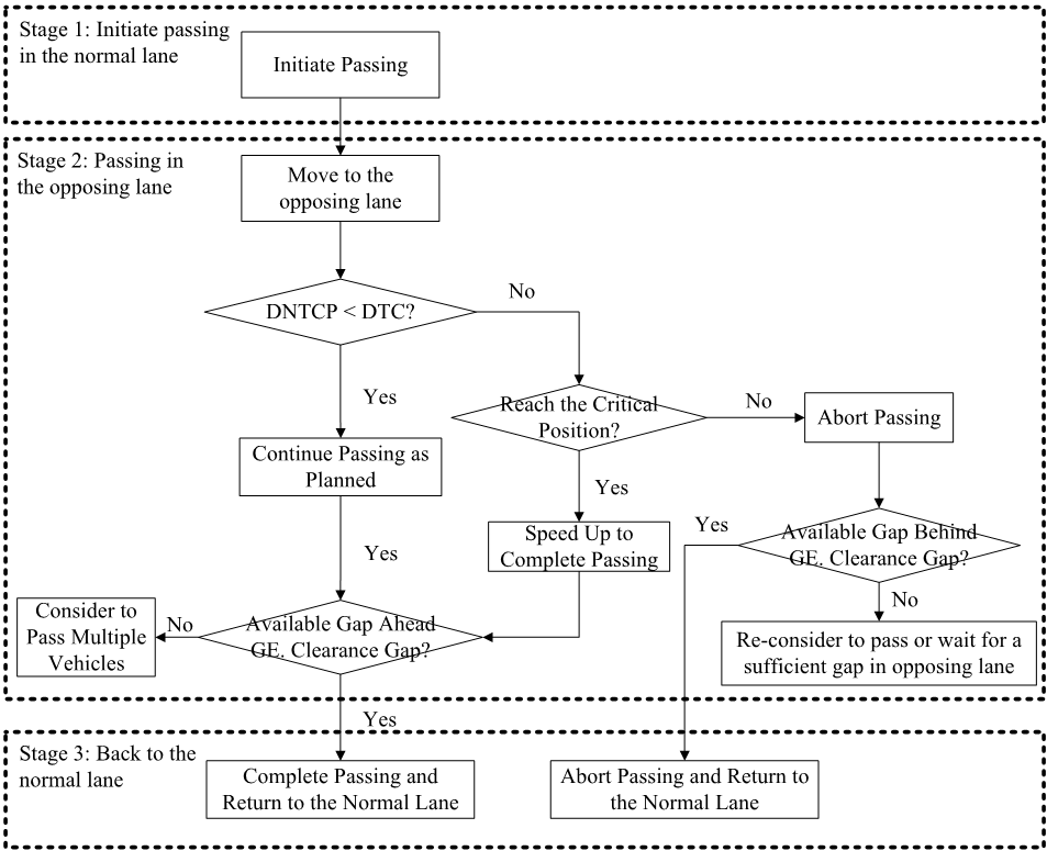
Figure 28.4: General Passing Manuever Process
Stage 1: Initiate passing in the normal lane
At the beginning of a passing maneuver, the potential passer starts to accelerate at the acceleration rate based on its own speed according to the first Table. At the same time, the potential passer moves over to the opposing lane.
Stage2: Passing in the opposing lane
After the potential passer moves into the opposing lane, it will keep on accelerating until it reaches a speed 12 mi/h (this value can be changed in the settings) greater than the speed of the vehicle being passed.5 Meanwhile, the variable \(DNTCP\) (distance needed to complete pass) is compared to the variable \(DTC\)6 (distance to collision with the oncoming vehicle) every time step (see the following figure for an illustration of these variables).
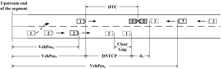
Figure 28.5: Illustration of DNTCP and DTC
As mentioned previously, before the passing maneuver is initiated, the \(DNTCP\) is equal to the PSD. However, once the passing maneuver is in progress, the \(DNTCP\) is continually changing (generally decreasing). For calculating \(DNTCP\), the time needed to complete passing (\(TNTCP\)) is first calculated. Since the potential passer will stop accelerating when its speed is 12 mi/h (i.e., 17.6 ft/s) greater than the vehicle being passed, the value of \(TNTCP\) is calculated by
\[ TNTCP=\left\{\begin{array}{l}\frac{-[{v_1}(t)-{v_2}(t)]}{({a_1}-{a_2})}+\frac{\sqrt{[{v_1}(t)-{v_2}(t)]^2-2({a_1}-{a_2})(VehPo{s_1}-VehPo{s_2}-ClearGap)}}{({a_1}-{a_2})},t<\frac{{v_2}(0)+17.6-{v_1}(0)}{{a_1}}+{t_0}\\ \frac{[{v_1}(t)-{v_2}(t)]}{{a_2}}-\frac{\sqrt{[{v_1}(t)-{v_2}(t)]^2+2{a_2}(VehPo{s_1}-VehPo{s_2}-ClearGap)}}{{a_2}},t \ge \frac{{v_2}(0)+17.6-{v_1}(0)}{{a_1}}+{t_0} \end{array}\right. \]
where:
\({TNTCP} = \text{time needed to complete pass (s),}\)
\({t_0} = \text{time step when the passing maneuver initiates (s),}\)
\({t} = \text{current time step (s),}\)
\({v_1}(t) = \text{speed of the passing vehicle at time step } t \text{ (ft/s),}\)
\({v_2}(t) = \text{speed of the vehicle being passed at time step } t \text{ (ft/s),}\)
\({v_1}(0) = \text{initial speed of the passing vehicle (ft/s),}\)
\({v_2}(0) = \text{initial speed of the vehicle being passed (ft/s),}\)
\({a_1} = \text{acceleration of the passing vehicle (ft/s}^2),\)
\({a_2} = \text{acceleration of the vehicle being passed (ft/s}^2),\)
\(VehPo{s_1} = \text{position of the passing vehicle relative to the upstream end of the segment at time step } t \text{ (ft), and}\)
\(VehPo{s_2} = \text{position of the vehicle being passed relative to the upstream end of the segment at time step } t \text{ (ft).}\)
Note that \(a_1\) is assumed to be a constant, while \(a_2\) is assumed to be 0, during the passing maneuver; thus, the calculation of \(TNTCP\) can be simplified as
\[ TNTCP=\left\{\begin{array}{l} \frac{-[{v_1}(t)-{v_2}(t)]}{{a_1}}+\frac{\sqrt{[{v_1}(t)-{v_2}(t)]^2-2{a_1}(VehPo{s_1}-VehPo{s_2}-ClearGap)}}{{a_1}},t-{t_0}<\frac{{v_2}(0)+17.6-{v_1}(0)}{{a_1}}\\ \frac{ClearGap-(VehPo{s_1}-VehPo{s_2})}{17.6},t-{t_0}\ge\frac{{v_2}(0)+17.6-{v_1}(0)}{{a_1}} \end{array}\right. \]
Once the \(TNTCP\) is obtained, the \(DNTCP\) can be calculated by
\[ DNTCP=\left\{\begin{array}{l} {v_1}(t)TNTCP+0.5{a_1}{(TNTCP)^2},t-{t_0}<\frac{{v_2}(0)+17.6-{v_1}(0)}{{a_1}}\\ {v_1}(t)TNTCP,t-{t_0}\ge\frac{{v_2}(0)+17.6-{v_1}(0)}{{a_1}} \end{array}\right. \]
For the computation of \(DTC\), the time to collision with the oncoming vehicle (\(TTC\)) is first calculated, given by
\[ TTC=\left\{\begin{array}{l} \frac{-[{v_1}(t)+{v_3}(t)]}{({a_1}+{a_3})}+\frac{{\sqrt{{[{v_1}(t)+{v_3}(t)]}^2}+2({a_1}+{a_3})(VehPo{s_1}-VehPo{s_3})}}{({a_1}+{a_3})},t<\frac{{{v_2}(0)+17.6-{v_1}(0)}}{{a_1}}+{t_0}\\ \frac{-[{v_1}(t)+{v_3}(t)]}{{a_3}}+\frac{\sqrt{[{v_1}(t)+{v_3}(t)]}^2+2{a_3}(VehPo{s_1}-VehPo{s_3})}{{a_3}},t\ge\frac{{v_2}(0)+17.6-{v_1}(0)}{{a_1}}+{t_0} \end{array}\right. \]
where:
\({TTC} = \text{time to collision with the oncoming vehicle (s),}\)
\({v_3}(t) = \text{speed of the oncoming vehicle at time step } t \text{ (ft/s),}\)
\({a_3} = \text{acceleration of the oncoming vehicle (ft/s}^2 \text{), and}\)
\(VehPo{s_3} = \text{position of the oncoming vehicle relative to the upstream end of the segment at time step } t \text{ (ft)}\).
Therefore, the \(DTC\) can be calculated by
\[ DTC=\left\{\begin{array}{l} {v_1}(t)TTC+0.5{a_1}{(TTC)^2},t-{t_0}<\frac{{{v_2}(0)+17.6-{v_1}(0)}}{{{a_1}}}\\ {v_1}(t)TTC,t-{t_0}\ge\frac{{{v_2}(0)+17.6-{v_1}(0)}}{{{a_1}}} \end{array}\right. \]
At every time step of the simulation, the value of \(DNTCP\) is compared to the value of \(DTC\). The result of this comparison leads to the following different situations that must be considered.
(1) DNTCP < DTC If the \(DNTCP\) is less than the \(DTC\), the passer will continue its passing maneuver as planned. Another issue related to the completion of passing is the gap size in front of the vehicle being passed, which is included in the calculation of \(DNTCP\). The passer requires a certain gap size to be able to return to the normal lane in order to complete passing. The default value for this gap size (i.e., ClearGap in above figure, Illustration of DNTCP and DTC) is 75 ft, but can be revised in the parameter settings. The passing vehicle only accepts the gap in front of the vehicle being passed if it is greater than or equal to the minimum gap.
(2) DNTCP ≥ DTC If the \(DNTCP\) is greater than or equal to the \(DTC\), the decision on whether the passing vehicle will continue or abort its passing maneuver is dependent on the relative position of the passing vehicle to the passed vehicle. If the passing vehicle has reached the critical position, the passing vehicle will continue its passing maneuver. If the passing vehicle has not reached the critical position, it will abort the passing maneuver. A study by Douglas W. Harwood and Glennon (1976) defined the critical position as the point at which the sight distances required to abort the pass and to complete the pass are equal. Two studies, one by Van Valkenburg and Michael (1971) and one by Weaver and Glennon (1972) independently recognized a key position of a passing maneuver occurs at the point where the passing driver can no longer safely abort the pass and is, therefore, committed to complete it. However, no unanimously accepted definition of the critical position currently exists. Douglas W. Harwood et al. (2008) suggests that the critical position can be considered to be the point when the passing vehicle and vehicle being passed are directly abreast of one another. This is the definition applied in the SwashSim logic.
The passer has not reached the critical position
If the passing vehicle has not yet reached the critical position when \(DNTCP\) is greater than \(DTC\), it will abort the passing maneuver. The process of returning to the normal lane is similar to that of completing a passing maneuver. The gap behind the vehicle being passed will be checked for the return. The minimum gap here is also set as three times the length of the passing vehicle, and the passing vehicle will only accept a gap greater than or equal to the minimum gap.The passer has reached the critical position
If the passer has reached the critical position when \(DNTCP\) is greater than \(DTC\), the passer will continue with completing the passing maneuver. In order to accommodate this without collision, the passing vehicle will speed up and/or the oncoming vehicle will decelerate. The specific amount of acceleration by the passing vehicle and/or deceleration by the oncoming vehicle is a function of the current acceleration rate of each vehicle, the passing vehicle’s acceleration capabilities, the oncoming vehicle’s deceleration capabilities, and the current \(DTC\) value.
Stage 3: Return to the normal lane
For a passing maneuver being completed, the passer will return to the normal lane in front of the vehicle being passed when the gap is sufficient. For an aborted passing maneuver, the passer will return to the normal lane behind the vehicle being passed if there is a sufficient gap. The existing mandatory lane changing logic in SwashSim is utilized for this situation. Under certain conditions, the passing vehicle will consider passing more than one vehicle. Specifically, if the passing vehicle’s speed is greater than the speed of the vehicle in front of the current vehicle being passed, and the gap in front of the current vehicle being passed is insufficient, the passing vehicle will attempt to pass the vehicle in front of the current vehicle being passed, subject to the logic and constraints as previously discussed.
28.3 Passing in a Passing Lane Section
A passing lane is defined as a lane added to improve passing opportunities in one direction of travel on a conventional two-lane highway. Although it may vary by jurisdiction, the logic implemented in this simulation program assumes that slower vehicles will move to the right lane in a passing lane section and the passing vehicles will pass on the left (usually this is indicated by a sign such as ‘Keep Right Unless Passing’). Ideally, each driver will drive following the guidance. However, it is recognized that this does not always happen; thus, the developed logic allows for the possibility of an impeding vehicle not moving over.
For each vehicle in a passing-lane section (hereafter referred to as the subject vehicle), the logic first checks the headway between this subject vehicle and the vehicle immediately behind, and then checks the headway between this subject vehicle and the vehicle immediately ahead. If the subject vehicle has a vehicle behind it in following mode (i.e., headway \(\leq\) follower headway threshold) and is not in following mode itself, the willingness to move over (WTMO) to the non-passing lane of the passing lane section for the subject vehicle will be considered. The value of WTMO is determined as follows:
\[ WTMO=\left\{\begin{array}{l} 0 &\mbox{if SVS > (FFS+5)}\\ \frac{FFS+5-SVS}{15} &\mbox{if (FFS - 10) < SVS < (FFS + 5)}\\ 1 &\mbox{if SVS < (FFS-10)}\end{array}\right. \]
where:
\({WTMO} = \text{willingness to move over (unitless),}\)
\({SVS} = \text{subject vehicle speed (mi/h), and}\)
\({FFS} = \text{free-flow speed (mi/h)}\)
This parameter will be adjusted by dividing by the square root of driver type if the length of the subject vehicle is less than 40 ft (the length of a single-unit truck), otherwise it remains as the original value (not dividing by the square root of driver type results in a higher probability to move over for trucks). The adjusted willingness to move over is compared to a generated uniform random number between 0 and 1, and if it is greater than the random number the subject vehicle will move over to the non-passing lane; otherwise, it will stay in the passing lane.
The existing SwashSim logic is utilized for determining when a vehicle will move from the lane being dropped at the end of the passing lane section back to the continuous lane. Generally, the discretionary lane change logic will apply for vehicles in this lane (either slow vehicles that moved out of the way, or faster vehicles that are trying pass slower vehicles that did not move over, or vice versa if the passing lane is the one that drops) until such a vehicle gets near to the end of the lane being dropped, in which case the mandatory lane change logic will be applied.
For computational efficiency reasons, this check is actually performed before the desire to pass calculations.↩︎
SwashSim does not compute available passing sight distance based on the specified roadway geometry; thus, it is necessary for the user to explicitly identify the allowable passing zones along the length of the highway.↩︎
Although definitions for the critical position vary, it can generally be considered to be the case when the passing vehicle and the vehicle being passed are abreast of one another.↩︎
Based on NCHRP Report 605 harwood_passing_2008↩︎
The \(DTC\) will be infinite when no oncoming vehicle is present↩︎