10 Signalized Intersections
This section discusses how traffic signal control settings are specified in SwashSim.
10.1 Traffic Control Screen
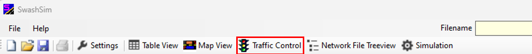
Figure 10.1: Toolbar Traffic Control Button
Pressing the ‘Traffic Control’ button on the toolbar will load the controller setup screen. Pressing the ‘Add Pretimed Controller’, ‘Add Actuated Signal Controller’ or ‘Add On-Ramp Signal Controller’ will add a signal controller entry to the table immediately below the button. Pressing the ‘Edit’ button for a given controller under the ‘Edit Timing Plan’ column will load the signal timing and phasing inputs screen (discussed below).
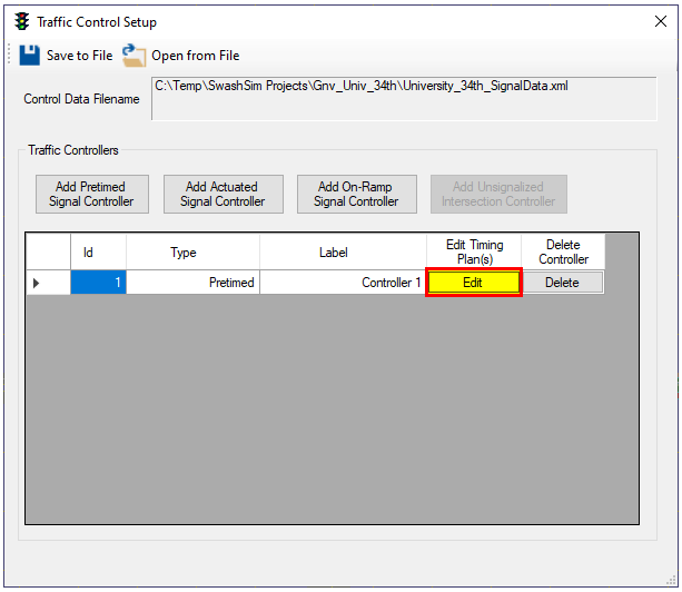
Figure 10.2: Traffic Control Main Screen
10.2 Pretimed Signal Phasing and Timing Inputs
Pressing the ‘Set Phasing & Timing’ button on the main inputs screen will load the ‘Signal Phasing and Timing Inputs’ screen.
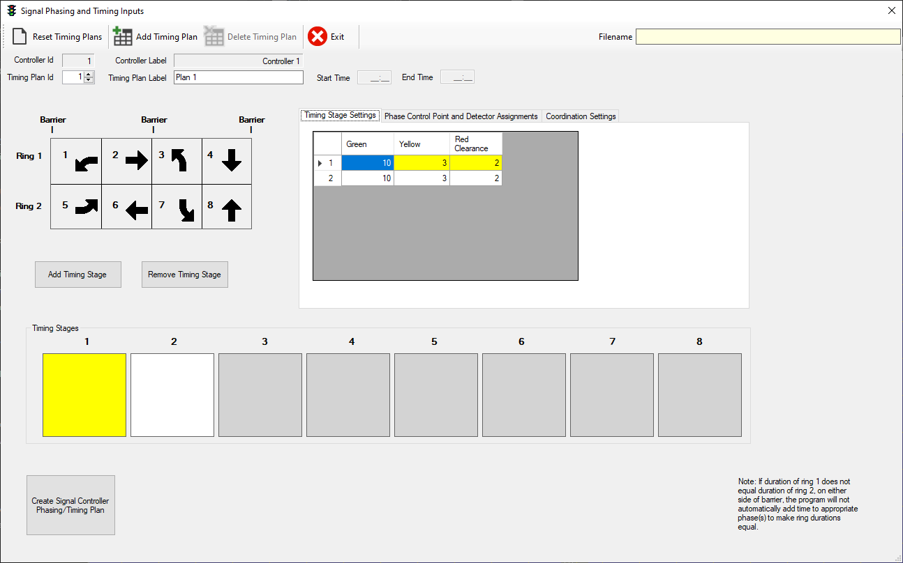
Figure 10.3: Pretimed Signal Controller Settings (1)
To add a timing stage, press the “Add Timing Stage” button. This will highlight the next available Timing Stage box in yellow. To edit a Timing Stage, click the desired stage so that it is highlighted in yellow. Timing stages are used to specify the phases (1-8) that will move (i.e., receive green) simultaneously. To add a traffic movement to the timing stage, click on the desired movement arrow(s) in the ring/barrier diagram. To remove a movement, click on the corresponding arrow in the ring/barrier diagram. If movement is selected that conflicts with another movement in that timing stage, an error message will appear and the movement arrow will not be added to the timing stage. For each timing stage, the green (G), yellow (Y), and all-red (AR) times need to be specified. To edit a timing interval, click on the appropriate table cell to highlight it in blue and type in the desired number. Press the ‘Tab’ or ‘Enter’ key to save edits. Note that the number in the left-most column corresponds to the timing stage number. The figure below shows an example timing stage plan.
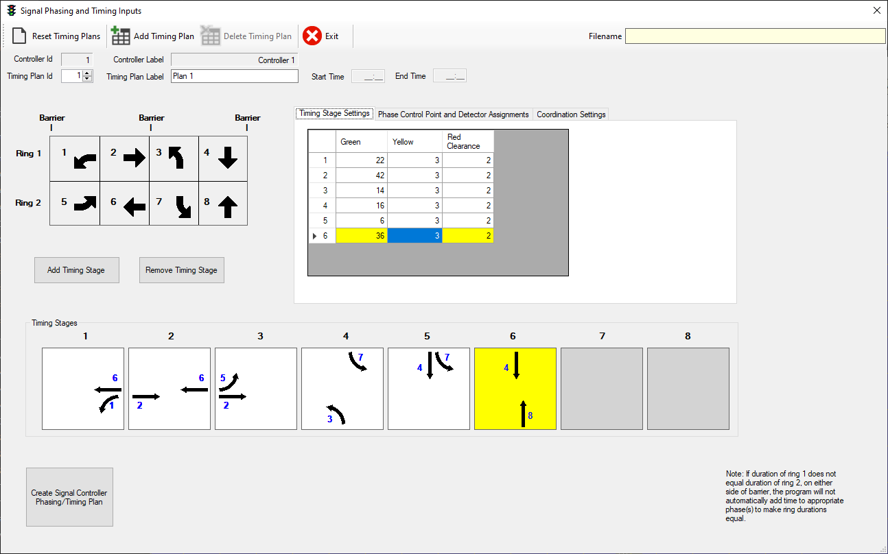
Figure 10.4: Pretimed Signal Controller Settings (2)
When the timing stage movements and corresponding interval times have been specified, the last step is to select ‘Create Signal Controller Phasing/Timing Plan’. This will generate a timing plan that is used by the dual-ring signal controller.
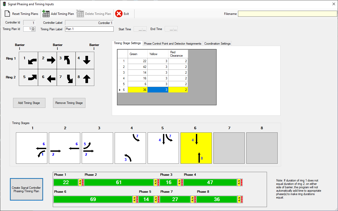
Figure 10.5: Pretimed Signal Controller Settings (3)
If revisions are made to the timing stages and/or interval times, press the ‘Create Signal Controller Phasing/Timing Plan’ again to create a new signal controller timing plan. The last timing plan that is generated is the one that is stored in memory. The simulation program will continue to store this timing plan in memory for the duration of the current session. If you want to save the timing plan to disk, press the “Save To File” button in the Traffic Control Setup screen after existing the controller settings screen.
10.2.1 Phase Control and Detector Assignments
Select the Phase Control and Detector Assignments tab to specify the signalized control points and/or detectors that associated with each signal phase.
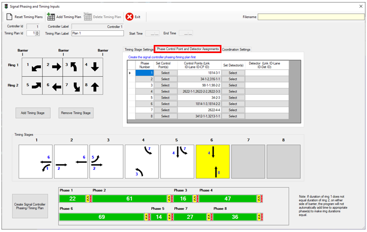
Figure 10.6: Pretimed Signal Controller Settings (4)
Pressing the Select button for a given phase will load the control points/detectors selection screen (an example for control points is shown in the following figure). After checking the desired control points/detectors and closing, the selections will be displayed in the table on the controller settings screen.
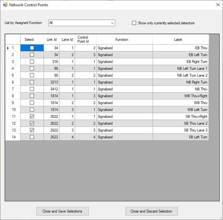
Figure 10.7: Traffic Signal Control Points Selection
10.2.2 Coordination Settings
Coordination settings can be specified under the corresponding tab. The inputs on this tab are as follows:
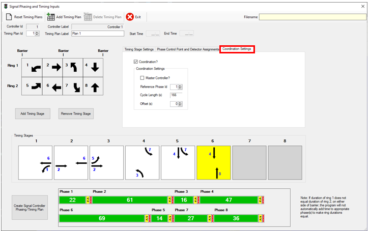
Figure 10.8: Pretimed Signal Controller Settings (5)
Coordination?: Check this box to enable coordination for the selected intersection controller
Master Controller?: This box should be checked for only one of the intersections among the group of intersections to which you are applying coordination settings. Generally, the intersection selected as the ‘Master’ should be the most upstream intersection for the direction of coordination. For example, if coordination is being set up for a series of four intersections for the eastbound direction of travel…
- -> (2) -> (3) -> (4)
intersection (1) should be selected as the master intersection.
- Reference Phase ID: This value corresponds to the phase number (1-8) of the coordinated movement. For example, if the eastbound through movement is being coordinated, this value should be set to ‘2’.
- Cycle Lengths (s): This value is calculated from the previously entered timing stage settings (green, yellow, all-red). It is for information purposes only and cannot be modified on this screen. If you return to the Timing Stage Settings tab and change any of the timing values there and then return to the Coordination Settings tab, the cycle length value will be updated accordingly.
- Offset(s): ** For the master intersection, this value should correspond to the number of seconds the coordinated phase starts relative to the start of the cycle (i.e., 0). For example, assume a timing plan starts with leading left turns for the eastbound and westbound approaches (phases 5 and 1) in timing stage 1, with a duration of 20 seconds (G+Y+AR), and then serves the eastbound and westbound through movements (phases 2 and 6) in timing stage 2. Assuming the coordinated movement is the eastbound through movement, the offset value should be set to 20; i.e., the coordinated movement starts 20 seconds after the start of the cycle, assuming a cycle start time of 0 seconds for the master intersection. ** For coordinated intersections downstream of the master intersection, the offset value should be set to the number of seconds that you want the reference phase to start after the start of the reference phase at the master intersection.
See (Mannering and Washburn 2019) for more information about signal coordination concepts.
10.3 Actuated Signal Control
After adding an actuated signal controller, press ‘Edit’ under ‘Edit Timing Plan’ to open the Timing Plan Data window.
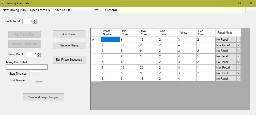
Figure 10.9: Actuated Signal Controller Settings (1)
Use the ‘Add Phase’ and ‘Remove Phase’ buttons to add and remove phases to the table on the right. To edit a phase, click on the desired cell so that it is highlighted blue, type the Phase Number (1 through 8) and press tab to move to the next cell. All cells except for Recall Mode should be numerical inputs and then use the drop-down menu to assign a recall mode for each phase. For more information on signal timing, see [[Traffic Signal Control Concepts#Basic Signal Timings|Basic Signal Timings]].

Figure 10.10: Timing Plan Data (Add, Remove Phase)
Once the phases are created in the table, then click on ‘Edit Phase Sequence’ to set phases to corresponding rings. Use the ‘Number of Rings’ drop down menu to select the number of rings to be used in the intersection. Then, in a similar manner in the Timing Plan Data window, use the ‘Add New Row’ and ‘Remove Current Row’ buttons to create a table for ring information. For the typical two-ring, eight-phase timing plan, insert six rows and then use the drop down menu to select ‘Barrier’ for rows three and six.
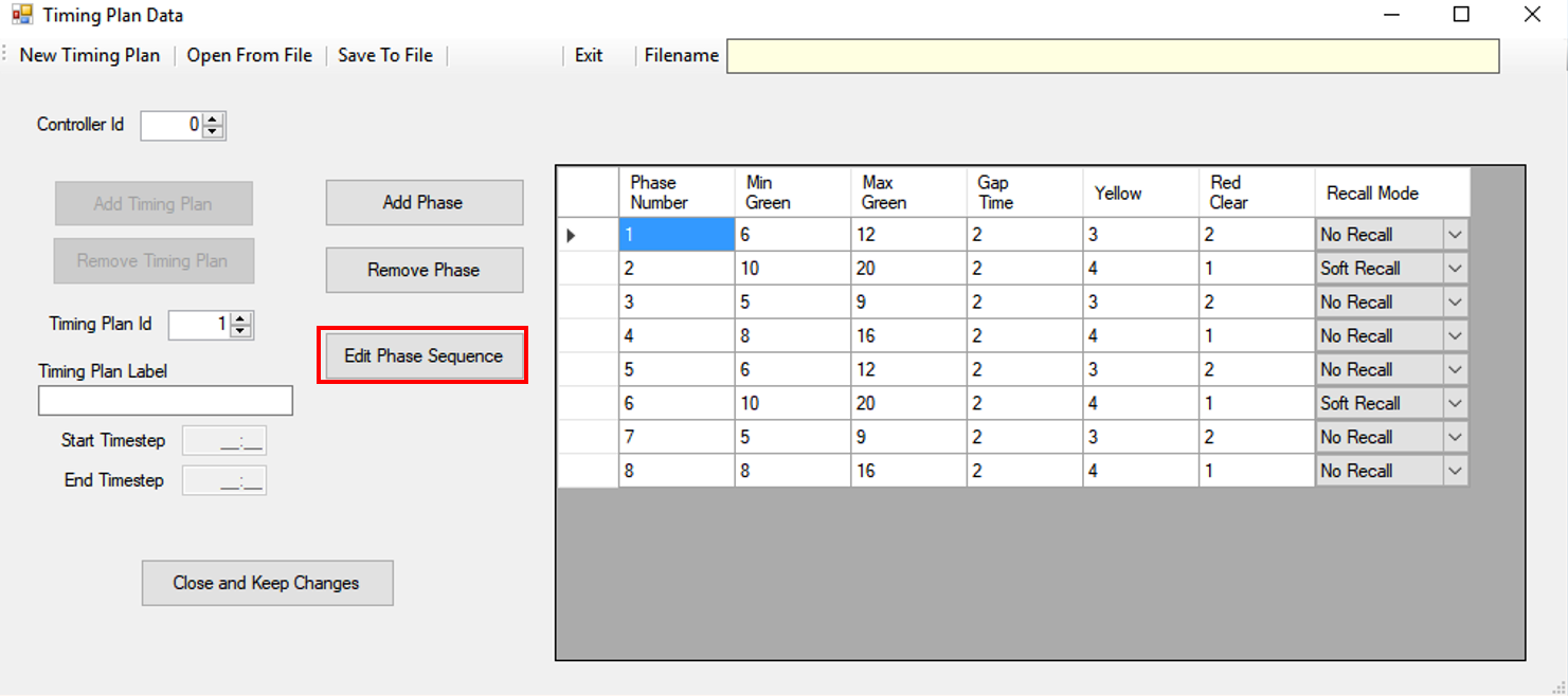
Figure 10.11: Timing Plan Data (Edit Phase Sequence)

Figure 10.12: Phase Sequence Inputs
Once the Phase Sequence Input table is complete, press ‘Close and Save Changes’.
10.3.1 Actuated Signal Controller File Setup
Before adding an actuated signal controller, all detectors and control points must be setup for the intersection(s). The next steps involve the editing of the actuated signal control files labeled ActControlPoints, ActDetectors, and ActTimingPlan. The following steps describe the process for editing the actuated signal control files in order to get actuated signal control to work properly in SwashSim. These files are plain text files and can be edited within any text editing program. Example files can be found in the Actuated Signal Control example project on the SwashSim GitHub site.
Once the actuated signal control files have been obtained, the first step is to set the directory location for the ControlPoints and Detectors files. This is done within the ActTimingPlan file. The following shows examples of this from an ActTimingPlan file.
<FilenameControlPoints>C:\Program Files\SwashWare\SwashSim\Projects\Signalized Intersections\Actuated\University_13th\ActControlPoints.xml</FilenameControlPoints>
<FilenameDetectors>C:\Program Files\SwashWare\Projects\Signalized Intersections\Actuated\University_13th\ActDetectors.xml</FilenameDetectors>
The next step is to edit the ActDetector file. This file is used to identify the detectors that are used by the actuated signal controller. The following shows an example of the code for one detector. Each detector at the intersection needs its own section of code.
<DetectorData>
  <Id>1</Id>
  <ControllerId>1</ControllerId>
  <ControlPhaseId>2</ControlPhaseId>
  <LinkId>56</LinkId>
  <LaneId>1</LaneId>
  <LanePositionBeginFeet>218</LanePositionBeginFeet>
  <LanePositionBeginPct>95</LanePositionBeginPct>
  <LengthFeet>6</LengthFeet>
  <LanePositionEndFeet>224</LanePositionEndFeet>
</DetectorData>- Id: the value should always be 1
- ControllerId: should be the controller number labeled on the timing plan data page
- ControlPhaseId: should correspond to the phase called by this detector
- LinkId: the link ID where this detector is located
- LaneId: the lane ID where this detector is located for the given link ID
- LanePositionBeginFeet: location of the detector within the link (as measured from upstream end of link)
- LanePostionBeginPct: location (as a percentage of the link length) of the detector within the link
- LengthFeet: length of detector in feet
- LanePositionEndFeet: the value of LanePositionBeginFeet + LengthFeet
The next step is to edit the ActControlPoints file. This files is used to identify the control points that are used by the actuated signal controller. The following shows an example of the code for one control point. Each control point at the intersection needs its own section of code.
<VehicleControlPointData>
  <Id>1</Id>
  <Control>Signalized</Control>
  <ControllerId>1</ControllerId>
  <ControlPhaseId>2</ControlPhaseId>
  <TravDir>NB</TravDir>
  <LinkId>56</LinkId>
  <LaneId>1</LaneId>
  <LaneIdsControlled>
    <unsignedByte>1</unsignedByte>
  </LaneIdsControlled>
  <PositionLaneFeet>223</PositionLaneFeet>
  <PositionLanePct>97</PositionLanePct>
</VehicleControlPointData>- Id: the value should always be 1
- Control: this value indicates what type of control mode applies for the control point–for a signalized intersection this will be set to “Signalized”
- ControllerId: should be the controller number labeled on the timing plan data page
- ControlPhaseId: should correspond to the phase called by this detector
- TravDir: indicates the direction of travel for vehicles passing this control point (EB,WB,NB,SB,NEB,NWB,SEB,SWB)
- LinkId: the link ID where this detector is located
- LaneId: the lane ID where this detector is located for the given link ID
- LanePositionBeginFeet: location of the detector within the link (as measured from upstream end of link)
- LanePostionBeginPct: location (as a percentage of the link length) of the detector within the link
- LaneIdsControlled: Same as LaneId
This completes the setup process for adding a new actuated signal controller to a SwashSim intersection project.