Chapter 5 HCM Weaving Segment Analysis
5.1 Introduction
Weaving is generally defined as the crossing of two or more traffic streams traveling in the same direction along a significant length of roadway, without the aid of traffic control devices.
Weaving areas are generally formed when a merge area is closely followed by a diverge area, or when an on-ramp is connected to an off-ramp with an auxiliary lane.
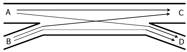
Figure 5.1: Weaving Flow Paths
Three geometric characteristics affect a weaving segment’s operating characteristics: length, width, and configuration.
5.2 Weaving Segment Length
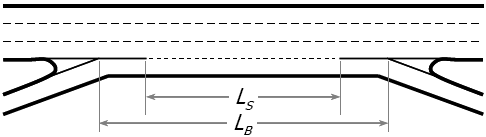
Figure 5.2: Weaving Lengths
The lengths illustrated are defined as follows:
- LS = Short length, the distance in feet between the end points of any barrier markings (solid white) that prohibit or discourage lane-changing. The minimum short length value to use in calculations in this methodology is 300 ft.
- LB = Base length, the distance in feet between points in the respective gore area where the left edge of the ramp traveled way and the right edge of the freeway traveled way meet.
Generally,
\[L_{S} = 0.77 \times L_{B}\]
5.4 Weaving Segment Configuration
Configuration refers to the way the entry and exit lanes are linked.
It dictates how many lane changes must be made to complete a weaving maneuver.
A one-sided weaving segment is one in which no weaving maneuvers require more than two lane changes to be completed successfully, and in which the on-ramp and off-ramp are located on the same side of the freeway.
A two-sided weaving segment is one in which at least one weaving maneuver requires three or more lane changes to be completed successfully or in which a single-lane on-ramp is closely followed by a single-lane off-ramp on the opposite side of the freeway.
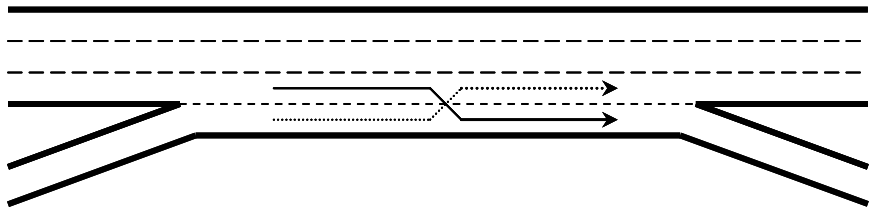
Figure 5.3: One-Sided Ramp Weave
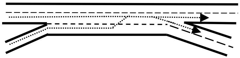
Figure 5.4: One-Sided Major Weave
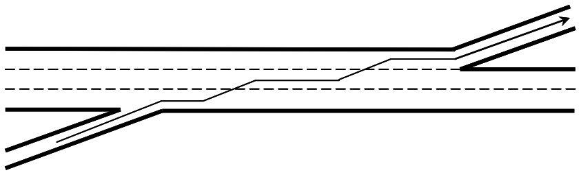
Figure 5.5: Two-Sided Weave with Single-Lane Ramps
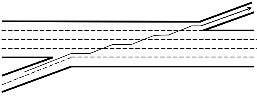
Figure 5.6: Two-Sided Weave with Three Lane Changes
5.5 Analysis Procedure
- Specify roadway and traffic conditions
- Calculate analysis flow rate using adjustment factors (i.e., PHF, \(f_{HV}\))
- Determine configuration characteristics
- Determine maximum weaving length
- Determine segment capacity
- Determine lane-changing rates
- Determine average speed of weaving and non-weaving vehicles
- Calculate density and determine LOS
5.5.2 Step 2
Calculate analysis flow rate:
\[v_{i} = \frac{V_{i}}{PHF \times f_{HV}}\tag{HCM Eq. 13-1}\]
where:
\(v_i =\) 15-min passenger car equivalent flow rate in pc/h,
\(V_i =\) hourly volume in veh/h,
\(PHF =\) peak-hour factor, and
\(f_{HV} =\) heavy-vehicle adjustment factor.
The subscript i is denoted as follows for the given movements:
FF = freeway-to-freeway,
FR = freeway-to-ramp,
RF = ramp-to-freeway,
RR = ramp-to-ramp,
W = weaving, and
NW = non-weaving.
5.5.3 Step 3
Determine configuration characteristics:
- \(LC_{RF} =\) minimum number of lane changes that must be made by one ramp-to-freeway vehicle to execute the desired maneuver successfully (lc),
- \(LC_{FR} =\) minimum number of lane changes that must be made by one freeway-to-ramp vehicle to execute the desired maneuver successfully (lc).
- \(LC_{RR} =\) is used for a two-sided weaving segment, instead of \(LC_{RF}\) and \(LC_{FR}\). It is set to the minimum number of lane changes that must be made by a ramp-to-ramp vehicle (lc). In Figure 5.5 this value would be 2. In Figure 5.6 this value would be 3.
- \(N_{WL} =\) number of lanes from which weaving maneuvers may be made with either one or no lane changes (ln). For a two-sided weaving segment, set \(N_{WL} = 0\).
For typical ramp-weave segment: \(N_{WL} = 2\)
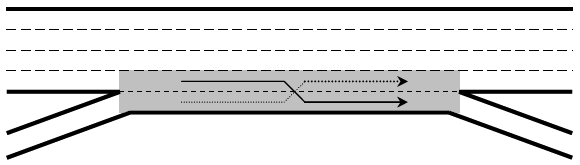
Figure 5.7: Number of Weaving Lanes
5.5.4 Step 4
Determine maximum weaving length.
- Is governed by point at which capacity is equal to basic segment capacity.
- Is a function of weaving/total volume ratio and number of weaving lanes.
\[L_{MAX} = \lbrack 5728\left(1 + VR \right)^{1.6}\rbrack - \left(1566 \times N_{WL} \right)\tag{HCM Eq. 13-4}\]
where \(VR = \frac{v_{W}}{v_{W}+v_{NW}}\).
If \(L_S < L_{MAX}\), the segment operates as a weaving segment; otherwise, analyze as separate ramp junctions and basic segment in between.
5.5.5 Step 5
Determine Segment Capacity:
- Based on density of 43 pc/mi/ln
\[c_{IWL} = c_{IFL} - \left\lbrack 438.2{(1 + VR)}^{1.6} \right\rbrack + \left\lbrack 0.0765 \times L_{S} \right\rbrack + \left\lbrack 119.8 \times N_{WL} \right\rbrack\tag{HCM Eq. 13-5}\]
where:
\(c_{IWL} =\) capacity of the weaving segment under equivalent ideal conditions, per lane (pc/h/ln),
\(c_{IFL} =\) capacity of a basic freeway segment with the same free-flow speed as the weaving segment under equivalent ideal conditions, per lane (pc/h/ln), and
\[c_{W} = c_{IWL} \times N \times f_{HV}\tag{HCM Eq. 13-6}\]
where \(c_W\) is the capacity of the weaving segment under prevailing conditions in vehicles per hour.
Based on weaving demand flow rates:
- for \(N_{WL} = 2\) lanes
\[c_{IW} = \frac{2400}{VR}\tag{HCM Eq. 13-7}\]
- for \(N_{WL} = 3\) lanes
\[c_{IW} = \frac{3500}{VR}\] \[c_{W} = c_{IW} \times f_{HV}\tag{HCM Eq. 13-8}\]
Calculate adjusted capacity:
\[c_{wa} = c_{w} \times CAF\tag{HCM Eq. 13-9}\]
where:
\(c_{wa} =\) adjusted capacity of weaving area (veh/h),
\(c_{w} =\) unadjusted capacity of weaving area (veh/h), and
\(CAF =\) capacity adjustment factor per HCM Chapter 11 (unitless). Default value is 1.0.
Calculate volume-to-capacity ratio:
\[v/c = \frac{v \times f_{HV}}{c_{wa}} \tag{HCM Eq. 13-10}\]
If the v/c is greater than 1.0, the segment is expected to fail, that is, have a LOS of F. In this case, this analysis methodology is not applicable. Instead, the analyst should consult the freeway facilities oversaturated conditions analysis methodology.
5.5.6 Step 6
Determine Lane-Changing Rates.
Estimate the total lane-changing rate for weaving vehicles:
\[{LC}_{W}={LC}_{MIN} + 0.39\lbrack\left(L_{S} - 300 \right)^{0.5} \times N^2 \times {(1 + ID)}^{0.8}\rbrack\tag{HCM Eq. 13-11}\]
where:
\(LC_{W} =\) equivalent hourly rate at which weaving vehicles make lane changes within the weaving segment (lc/h);
\(LC_{MIN} =\) minimum equivalent hourly rate at which weaving vehicles must make lane changes within the weaving segment to successfully complete all weaving maneuvers (lc/h);
\(L_{S} =\) length of the weaving segment, using the short length definition (ft); Again, 300 ft is the minimum value;
\(N =\) number of lanes within the weaving segment; and
\(ID =\) interchange density (int/mi).
\[{LC}_{MIN} =\left({LC}_{RF}\times v_{RF} \right) + \left({LC}_{FR} \times v_{FR} \right)\tag{HCM Eq. 13-2, 1-sided}\] \[{LC}_{MIN} =\left({LC}_{RR}\times v_{RR} \right)\tag{HCM Eq. 13-3, 2-sided}\]
Estimate the total lane-changing rate for non-weaving vehicles:
- Calculate non-weaving vehicle index:
\[I_{NW} = \frac{L_{S} \times ID \times v_{NW}}{10,000}\tag{HCM Eq. 13-12}\]
- Calculate \(LC_{NW1}\)
\[LC_{NW1} = \left(0.206 \times v_{NW} \right) + \left(0.542 \times L_{S} \right) - (192.6 \times N)\tag{HCM Eq. 13-13}\]
- Calculate \(LC_{NW2}\)
\[LC_{NW2} = 2,135 + 0.223(v_{NW}-2000)\tag{HCM Eq. 13-14}\]
- Calculate \(LC_{NW3}\)
\[LC_{NW3} = LC_{NW1} + (LC_{NW2}-LC_{NW1}) \left(\frac{I_{NW} - 1300}{650}\right) \tag{HCM Eq. 13-15}\]
- Set non-weaving vehicle lane changing rate equal to appropriate value:
\[\tag{HCM Eq. 13-16}\]
If \(I_{NW} \leq 1,300: LC_{NW} = LC_{NW1}\)
If \(I_{NW} \geq 1,950: LC_{NW} = LC_{NW2}\)
If \(1,300 < I_{NW} < 1,950: LC_{NW} = LC_{NW3}\)
If \(LC_{NW1} \geq LC_{NW2}: LC_{NW} = LC_{NW2}\)
Calculate total lane changing rate:
\[{LC}_{ALL} = {LC}_{W} + {LC}_{NW}\tag{HCM Eq. 13-17}\]
5.5.7 Step 7
Determine average speeds for weaving and non-weaving vehicles:
- Weaving:
\[S_{W} = 15 + \left(\frac{FFS - 15}{1 + W} \right)\tag{HCM Eq. 13-19}\] \[W = 0.226\left(\frac{LC_{ALL}}{L_{S}} \right)^{0.789}\tag{HCM Eq. 13-20}\]
- Non-Weaving:
\[S_{NW} = FFS - \left(0.0072 \times LC_{MIN} \right) - \left(0.0048 \times \frac{v}{N} \right)\tag{HCM Eq. 13-21}\]
Determine average speed for all vehicles:
\[S = \frac{v_{W} + v_{NW}}{\left(\frac{v_{W}}{S_{W}} \right) + \left(\frac{v_{NW}}{S_{NW}} \right)}\tag{HCM Eq. 13-22}\]
5.5.8 Step 8
Calculate density and LOS.
\[D = \frac{\left(\frac{v}{N} \right)}{S}\tag{HCM Eq. 13-23}\]
v = total demand flow rate in the weaving segment (pc/h), \(v = v_{W} + v_{NW}\)
- Exhibit 13-6 Density (pc/mi/ln) LOS Thresholds
| Level of Service | Freeway Weaving Segments | Weaving Segments on Multilane Highways or C-D Roads |
|---|---|---|
| A | 0-10 | 0-12 |
| B | > 10-20 | > 12-24 |
| C | > 20-28 | > 24-32 |
| D | > 28-35 | > 32-36 |
| E | > 35-43 | > 36-40 |
| F | > 43 or Demand exceeds capacity | > 40 or Demand exceeds capacity |
5.6 References
Transportation Research Board (2022). Highway Capacity Manual, 7th Edition: A Guide for Multimodal Mobility Analysis. Transportation Research Board, Washington, DC. https://nap.nationalacademies.org/catalog/26432/highway-capacity-manual-7th-edition-a-guide-for-multimodal-mobility